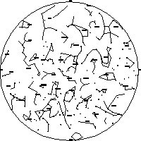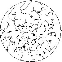

This page presents the formulas needed to plot a whole horizon
chart in stereographic projection for your latitude and a given
sidereal time. You can download a working program in QBASIC that
produces a PostScript file that plots a basic chart, or you can use your
programming skills to enhance my simple efforts. I assume that you are familiar
with the basics of astronomical coordinates, if not, you might want to print out
and read Nick
Strobel's excellent primer. It would only take an hour or so.
If you just need a chart now I would recommend
Horizon charts show the whole of your night sky at one time - the entire celestial hemisphere visible to you is represented as a small circle on a piece of paper. These charts can be found in astronomy magazines, in newspapers, and versions are available on the Net. Being curious about such things, I set out to see how to calculate one. My version is very rough compared to published ones, however I can customise the chart and there is no copyright!
The main steps are
I used a selection of the brightest 1000 stars from the Yale Bright Star
Catalog 5th edition. I removed most of the information about these stars and
retained only the coordinates and the visual magnitude. For the constellation
figures and the labels, I scavenged two files from John Walker's Home Planet.
All the files you need can be found in the QBASIC section on this
page. I have used the stereographic projection as this projection preserves the
shapes of the constellations near the horizon, and I outline a simple system for
'clipping' lines at the horizon.
[ Top ]
Sidereal time runs roughly 4 minutes per day faster than UT. If you look up at the sky at the same civil time each day, you will notice that the constellations change from month to month. Equally, if you stay up till the early hours of the next morning, you will see the sky as it will be in the evening in a few months time. If we draw a set of 12 horizon charts at two hour intervals of sidereal time, then we can use those charts in two ways:
Sidereal time at various local times on the 4th/5th of each month
(Not daylight saving time!)

 LT   Jan   Feb   Mar   Apr   May   Jun   Jul   Aug   Sep   Oct   Nov   Dec
 7pm   2     4     6     8     10    12    14    16    18    20    22    0
 9pm   4     6     8     10    12    14    16    18    20    22     0    2
11pm   6     8     10    12    14    16    18    20    22     0     2    4
 1am   8     10    12    14    16    18    20    22     0     2     4    6

On the 19th/20th of each month, use the same charts, but they are
valid for one hour local time earlier.

Examples

1. 10pm BST on July 4th - local time is 9pm, so use chart for 16h
   sidereal time

2. 4am 20th Feb. - Same as 5am on Feb 5th, so go for sidereal 14h chart.

(Max error 10 minutes in LST for 2001)
[ Top ]
We just use the following formulas taken from another page in this site (I use a very slightly different version in the QBASIC program).
Hour angle
----------

HA = LST - RA

If HA negative, then add 360 to bring in range 0 to 360
RA must be in degrees.
Altitude
--------

sin(ALT) = sin(DEC)*sin(LAT)+cos(DEC)*cos(LAT)*cos(HA)

ALT = asin(ALT)

Aziumuth
--------

               sin(DEC) - sin(ALT)*sin(LAT)
cos(A)   =   ---------------------------------
                   cos(ALT)*cos(LAT)

A = acos(A)

If sin(HA) is negative, then AZ = A, otherwise
AZ = 360 - A
[ Top ]
There are many ways of 'mapping' (in the literal sense) the hemisphere of the sky onto a flat piece of paper. Planispheres often use the polar azimuthal projection, where the pivot is the North Celestial Pole, and equally spaced concentric circles represent the declination. Great and small circles that have the NCP as their pole are represented by circles, and the RA colures are straight lines. Other circles follow more complex curves, and the constellation figures become very distorted as the declination drops below -30 or so.
The Stereographic projection preserves angles, so that the constellation figures look familiar near the horizon - the figures just become very large. Because angles are preserved, you can draw in all the 'Big Dipper curves' people use to remember the position of various asterisms. Any circle on the celestial sphere can be represented by a circle in the stereographic projection plane, but with modified centre and radius, so it should be easy to add circles representing the ecliptic, lines of RA and Dec and so forth. The formulas for the X,Y coordinates in the plane of projection for a point with given horizon coordinates are quite simple.
x = COS(z) * TAN((90 - a) / 2)
y = SIN(z) * TAN((90 - a) / 2)

where a is altitude and z is azimuth of the star. These formulas
will actually give North along the X axis.

90 - a is simply the Zenith angle of the star, and the Zenith is
the centre of your plot.
[ Top ]
Whole sky charts have 'stick figures' representing the main asterisms in each constellations drawn in to aid identification. At any given sidereal time some of the familiar figures will lie across the horizon, either partially risen or partially set. The data file called conlines.dat scavenged from John Walker's Home Planet program represents the stick figures as a series of single line segments. The file gives the RA and DEC of the two points at either end of each line. Strictly speaking, I suppose that the figures should project as arcs of large circles in the projection plane - Guy Ottewell uses curves in the whole sky charts in his excellent Astronomical Calendar. I chose to keep things simple and just project the points as stars and then draw lines between them.
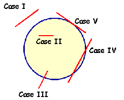
Considering a single line segment, there are 5 possible cases that describe the possible relationship between the segment and the horizon - they are summarised below. Cases IV and V are not trapped in this simple program.
[ Top ]

[ Top ]
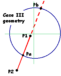
We have a line segment with end point P2 outside the horizon circle and endpoint P1 inside the horizon circle. We need to calculate the coordinates of Pa - the point of intersection with the horizon circle that lies between the two points, and we need to reject the other intersection point Pb that lies outside the two end points along an extended line segment. Then you draw the clipped constellation line from Pa to P1 in the usual way. In the formulas below, the coordinates of P1 in the projection plane are x1, y1 and so on referred to an origin at the centre of the horizon circle. The horizon circle has a radius of 1 in this case.

The coordinates of points that lie along the line P1, P2 are described by the 'equation of a straight line' Y = mX + K, where m is the gradient of the line, and K is the Y coordinate of the line when X=0 (when the line crosses the Y axis). The equation of the horizon circle is X^2 + Y^2 = 1 where X^2 means 'X squared'. The coordinates of the two intersection points Pa and Pb will be solutions of a simultaneous equation, and we can identify the intersection point that lies within the line segment by requiring that the coordinates of Pa lie between the coordinates of P2 and P1.
The algebra follows...
Gradient m of line through P1, Pa, P2, Pb

m = (Y2 - Y1) / (X2 - X1)

Intercept K of the line

K = Y1 - mX1

(just pick a point with known coordinates and solve a simple equation in K)

The coordinates of Pa and Pb satisfy the simultaneous equations

Y^2 + X^2 = 1     [1]
Y = mX + K        [2]

Eliminating Y by putting Y = mX + K in [1]

(mX + K)^2 + X^2 = 1

Multiplying out the bracket and arranging like a canonical quadratic
equation (is this bringing back happy memories of school days yet?)
we get

(m^2 +1)X^2 + 2mKX + K^2 - 1 = 0

This quadratic has two solutions. The formula for the two possible
values of X in the general quadratic aX^2 +bx + c=0 is:

X = (-b + sqrt(b^2 - 4ac))/ (2a) and
X = (-b - sqrt(b^2 - 4ac))/ (2a)

Equating the coefficients of our quadratic above with the a,b,c gives

a = m^2 + 1
b = 2mK
c = K^2 - 1

To solve for a particular set of points, just work out the values of
the two possible roots, say Xp and Xq, then substitute back into [2]
for the corresponding Yp and Yq

Yp = mXp + K    and   Yq = mXq + K

Then we need to decide which pair of coordinates corresponds to the
point Pa. The coordinates of Pa will satisfy the inequalities...

(X1 < Xa < X2 OR X2 < Xa < X1) AND (Y1 < Ya < Y2 OR Y2 < Ya < Y1)

Testing for this condition requries a certain amount of jiggery
pokery (see the QBASIC program for an example)- basically you have
to allow for the line segment having positive or negative slope, and
so the X1 and X2 coordinates can be opposite in order.

If the gradient of the line segment happens to be exactly zero, then
the second inequality will never be satisfied and the line won't get
plotted in my current QBASIC implementation.
[ Top ]
Running the QBASIC program with Case III clipping suggests that only about 20 to 30 lines are clipped in each horizon map. Cases IV and V are likely to be a lot less common for the following reasons
If you decide that you do want to trap and deal with cases IV and V, you will need to
You need to download the first 4 files below to be able to plot a chart. The last file is a sample of the PS output converted to PDF using Ghostscript. I have added functions that will create a filled circle (for the stars) and print constellation labels that are rotated around the Zenith.
The program consists of four loops, one for star plotting, one for constellation figures, one for the constellation labels, and one for printing the Beyer star letters near appropriate stars. The last two loops could be combined. The stars are not plotted if they are below the horizon, and for the constellation lines cases II and III (above) are fully implemented. A typical loop looks like this
Labels and Beyer letters are plotted very much like the stars, based on a 'fiducial point' for each label - usually the bottom left coordinate of a box surrounding the label. This results in some labels being printed outside the horizon circle. The notorious 'labelling problem' arises - star labels can overlap the star coordinates and the constellation names. One way of displacing the beyer letters would be to retain the magnitude information for the named star and displace the label by an amount equal to the radius of the star circle. I shall try this in a future version! For now, a simple 'nudge' is applied to each letter to shift it slightly away from the star along a line of 45 degrees to the star.
I have only implemented 'case III' clipping as the occurence of cases IV and V is statistically small (I think). The constellation lines loop looks a bit like this
The plotted flag is probably redundant but could be useful if you want to trap Cases IV and V. In the QBASIC program, I do not explicitly allow for the case where the gradient of the line segent is zero. This may cause a line to be rejected - the whole line would not be plotted in this case. I shall address this logic error before adding in the constellation boundaries!
The routines that produce the PostScript were contributed by Robert Lane for the Planisphere page, except for the dText and dTextRotate function hacks for which I take the blame. You should be able to edit the data files to reduce the complexity of the charts, or focus on small details (say the relative positions of the big and little dippers over time) for illustrative purposes.
I have not done much in the way of systematic checking. I have printed a chart for latitude 40 North and 9h of siderial time and compared this carefully with the March chart in Guy Ottewells 1999 Astronomical Calendar, as well as the 1h chart. The charts seem to match pretty well, and Ottewell is using the Stereographic projection.
[ Root ]
Last Modified 16th March 2001
Keith Burnett